Solar panels: documenting them on the diagram and the plan
Panels, inverter, wiring and protective devices, chapter 7.112 of Book 1: what the diagram, the plan and the file contain for a PV installation.
A photovoltaic installation is a source: it belongs on the single-line diagram and on the position plan, just like the dwelling’s circuits. Book 1 of the RGIE provides for this in section 3.1.2, and its chapter 7.112 adds measures specific to low-voltage domestic photovoltaic installations (≤ 10 kVA). Here is what must appear in the file when an installation produces electricity, and how to put it there properly.
What changes when the installation produces
As long as a dwelling only consumes, current flows from the grid to the circuits. With PV, the installation also becomes a source, operating in parallel with the grid. For chapter 7.112 installations, Book 1 requires signs warning of the dangers of electricity, supplemented with the indications « Ne pas déconnecter en charge » (do not disconnect under load) and « Installation électrique toujours sous tension » (electrical installation always live) or equivalent, placed in appropriate locations.
The file must reflect that reality. A single-line diagram that shows only the consumption side of a house fitted with panels is incomplete: subsection 3.1.2.2 lists sources, including the solar panel, the inverter and the battery, among the elements that single-line diagrams contain at a minimum.
The elements to show on the diagram
For a domestic installation, subsection 3.1.2.2 lists what single-line diagrams contain at a minimum. Applied to PV, this gives:
- The sources: the solar panels and the inverter, which the text names explicitly.
- The wiring, on the DC side as well as the AC side: type, cross-section, number of conductors and installation method.
- The protective devices: type and characteristics of the RCDs and overcurrent protective devices in this part of the installation, on the DC side as well as the AC side, if any.
- Switches and boxes: any connection or junction boxes in this part of the installation.
- The connection to the board: the place where the inverter’s circuit arrives. The text does not name it as such, but it is what shows how production and consumption coexist.
The reading test: a colleague discovering your diagram must be able to follow the current from the panel to the board: panels, DC wiring, inverter, AC-side protective devices, connection. If a link is missing, they have to guess.
The file goes beyond the diagram. For chapter 7.112 photovoltaic installations, section 9.1.2 adds the user manuals (operation and maintenance), the safety instructions for working on the installation and using it, and the references and technical characteristics of the installed equipment (make, model, power…).
Chapter 7.112 and the inspection
Chapter 7.112 applies to low-voltage domestic photovoltaic installations (≤ 10 kVA). It supplements the general requirements of the other parts of Book 1, which still apply. Its specific measures are:
- making the file elements provided for in section 9.1.2 available to any person concerned;
- marking the DC conductors and the live AC conductors;
- placing the warning signs described above;
- earthing the metal frames of the modules and their structures, unless the manufacturer prohibits it, with a protective conductor whose cross-section is at least equal to that of the protective conductor of the AC supply, with a minimum of 2.5 mm² if it has mechanical protection and 4 mm² if it does not.
During the conformity inspection or a periodic inspection visit of a domestic photovoltaic installation, the tests carried out by the accredited inspection body also cover, under section 7.112.3, the disconnection of the automatic isolation system when grid voltage is lost (in less than 5 seconds), the absence of production to the grid until its voltage returns, and automatic disconnection of supply: testing the RCDs with their test button and checking the fault loops and the correct connection of the RCDs, using a fault current of at least once their rated sensitivity. The report also states the number and rated power of the modules, and the number, type, serial number and maximum AC power of the inverters (section 7.112.4). All data worth having ready in the file. Our inspection checklist details how the visit unfolds.
The position plan too
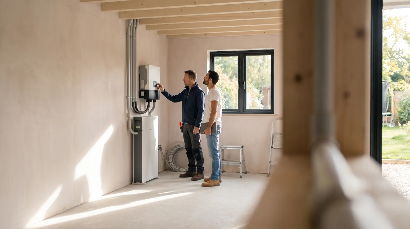
Under subsection 3.1.2.3, the position plan of a domestic installation shows the position of the sources mentioned on the single-line diagram, including the solar panel and the inverter, just like the boards, sockets, lighting points and fixed appliances. The inverter therefore goes at its actual location: attic, garage, utility room.
There is an exception for the existing parts of domestic electrical installations whose on-site execution took place from 1 October 1981 onwards and which underwent a conformity examination under the former RGIE: section 8.2.2 (point 7) allows, by derogation from point a of subsection 3.1.2.3, low-voltage domestic photovoltaic installations (≤ 10 kVA) to have only a written description, possibly supplemented with photos.
Think about consistent referencing too. Book 1 (subsection 3.1.2.1) identifies each elementary circuit on the diagram with a letter, which is carried over to the position plan. The control, protective and isolation devices of circuits are marked clearly, visibly and indelibly, unless any possibility of confusion is ruled out (subsection 3.1.3.1): using the same identifier as on the diagram avoids any ambiguity.
What not to forget
- PV added, never documented. Section 3.1.2 requires diagrams, plans and documents to be kept up to date, and any modification or extension to appear on the position plan, which shows the existing situation at all times. See also our article on the electrical file when selling.
- The inverter replaced without an update. If the file still shows the old model and the old power, it no longer matches the installation.
- The DC part missing. The diagram shows an "inverter" circuit on the AC side and nothing else: the panels and the DC wiring have vanished from the drawing.
- A vague connection. The production is drawn somewhere in the board, with no way of telling behind which protective device it actually arrives.
The remedy remains to document at the moment of installation, not years later from memory. With Amperio, each element, drawn or dictated on site, lands in the right room on the plan, always consistent with the single-line diagram.
Sources
- RGIE, Book 1, section 3.1.2 (FPS Economy, version of 29.10.2025)
- RGIE, Book 1, chapter 7.112 (FPS Economy, version of 29.10.2025)
- RGIE, Book 1, section 9.1.2 (FPS Economy, version of 29.10.2025)
- RGIE, Book 1, section 3.1.3 (FPS Economy, version of 29.10.2025)
- RGIE, Book 1, section 8.2.2 (FPS Economy, version of 29.10.2025)
This article is informative. It replaces neither the RGIE (Book 1) nor the advice of your inspection body.
A free job site for 7 days, no credit card.