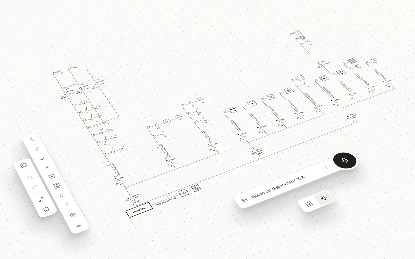
Drawing a position plan, room by room
The 4-step method for a clear position plan: base plan, electrical points, circuit referencing and the final check, in line with Book 1 of the RGIE.
The position plan is, with the single-line diagram, one of the two documents Book 1 of the RGIE requires for every new domestic electrical installation and every significant modification or significant extension (subsection 3.1.2.1). It shows where each part of the installation is located, and the compliance inspection report certifies that the installation has been carried out in accordance with the single-line diagrams and position plans (subsection 6.4.6.4). Here is a four-step method for a complete plan that is consistent with the diagram.
What the position plan is, and what it is not
Chapter 2.12 of Book 1 defines a plan as a graphic representation that shows, to scale, the geographical position of the various parts of an installation, and the position plan as the plan that shows the position of the various parts of the installation. For a domestic installation, subsection 3.1.2.3 specifies that it shows the position of the distribution boards, connection and junction boxes, socket-outlets, lighting points, switches, fixed machines and appliances and sources that appear on the single-line diagram.
It is not an architect’s plan: that list includes neither dimensions nor furniture. Nor is it a wiring plan: the route of the cables through the walls is not part of it. The diagram says how the circuits are made up and protected, the plan says where their items are, and the same referencing ties the two together.
Step 1: a base plan to scale
Start with the outline of the dwelling and the partition walls, level by level. Since a plan is defined as a representation to scale, work from reliable dimensions. Three possible sources, from the quickest to the most laborious:
- An existing plan: the architect’s plan, the sales plan, an old file. Check on site that it still matches the partition walls.
- A dimensioned sketch on site: room by room, with the main measurements, to be redrawn to scale afterwards.
- A full survey: when nothing else exists and the dwelling is complex.
Bear in mind that, for the inspection visit at the sale of an old installation (section 8.4.2), Book 1 specifies that the summary freehand sketch drawn up by the accredited body cannot be used as a position plan. Name each room on the base plan: kitchen, hall, bedroom 1. These labels serve as reference points for the whole file.
Step 2: place the items, room by room
Then walk through the dwelling in a fixed order, for example clockwise on each level, and place in each room the items listed in subsection 3.1.2.3:
- The socket-outlets, distinguishing single from multiple, including those hidden behind appliances.
- The lighting points, on the ceiling as well as on the walls.
- The switches, noting which switch controls which lighting point, including two-way switches between the two entrances of the same room.
- The fixed machines and appliances: for example water heater, cooker hood, boiler.
- The distribution boards, connection and junction boxes, and any sources, such as an inverter.
Use the symbols of table 2.23 (chapter 2.13) from the first draft rather than a personal code to transcribe later: our guide to the essential symbols and their pitfalls goes through them.
The fixed order ensures no room gets skipped when the survey is interrupted. Finish each room completely, sockets, lighting, controls, appliances, before moving to the next, and tick it off on the base plan.
Step 3: carry over the diagram’s referencing
Book 1 lays down the referencing (subsection 3.1.2.1). On the single-line diagram, each elementary circuit receives a capital letter, and each lighting point, socket-outlet and control unit an order number, starting from the overcurrent protective device. On the position plan, each lighting point, socket-outlet and control unit carries the letter of its circuit and its order number from the diagram; each switch carries the letter of its circuit and the number of the point it controls.
On an existing installation, establish which circuit each item belongs to before giving it a reference: a guessed reference makes both documents wrong. For the existing parts of an old domestic installation, carried out on site before 1 October 1981, section 8.2.1 (point 7) allows a simplified position plan for which referencing is not necessary, and does not require the single-line diagrams and position plans to match; how this applies to a specific installation is for the accredited body to decide.
It is also the step that dictation speeds up: in Amperio, each item, dictated or placed by hand, lands in the right room, and the plan and the diagram are updated together, as our article on dictating your job site shows.
Step 4: check the match
Before printing, cross-check the two documents in both directions: each item listed in subsection 3.1.2.3 that is shown on the diagram must appear on the plan, with the same reference for the numbered points, and each item on the plan must correspond to an item on the diagram. Subsection 3.1.2.1 adds that every modification or extension of a domestic installation is shown on the position plan, which gives the existing situation at all times: the plan is updated with every intervention.
What tends to be missed
Beyond the living rooms, check in particular:
- The secondary rooms: cellar, garage, attic, laundry room. They have electrical items, so they belong on the plan.
- The outdoors: facade lighting, terrace socket, the feed to the garden shed or the gate.
- Less visible items: the socket behind the dishwasher, the roller shutter feed, the bell, junction boxes.
- The levels: one view per level, converted attic included.
The walk-through test: mentally retrace your way around the dwelling, plan in hand, counting the items in each room. If a room on the plan is empty even though it has lighting, something is missing.
Sources
- RGIE, Book 1, section 2.12 (FPS Economy, version of 29.10.2025)
- RGIE, Book 1, section 2.13 (FPS Economy, version of 29.10.2025)
- RGIE, Book 1, section 3.1.2 (FPS Economy, version of 29.10.2025)
- RGIE, Book 1, section 6.4.6 (FPS Economy, version of 29.10.2025)
- RGIE, Book 1, section 8.2.1 (FPS Economy, version of 29.10.2025)
- RGIE, Book 1, section 8.4.2 (FPS Economy, version of 29.10.2025)
This article is informative. It replaces neither the RGIE (Book 1) nor the advice of your inspection body.
A free job site for 7 days, no credit card.